 English
 中文简体
中文简体 русский
We are committed to providing customers with high-quality, precision mold solutions.
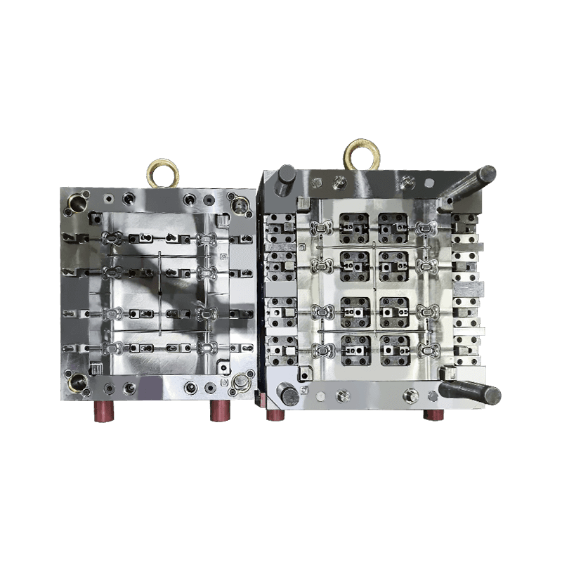
Toolbox Molds
Cat:Toolbox And Accessories Mold
Toolbox molds encompass a variety of types designed to produce different styles and sizes of toolbox...
See Details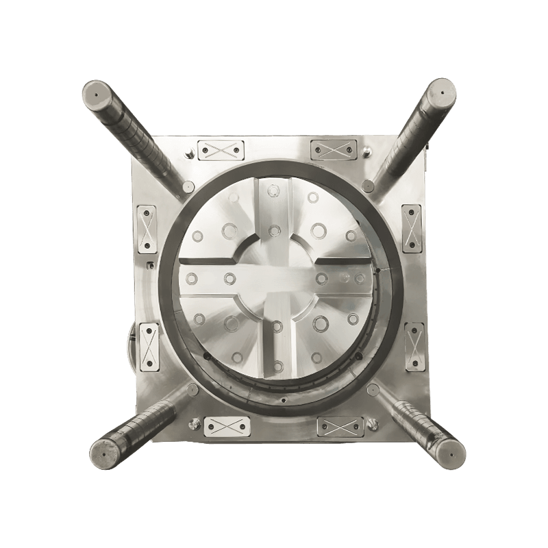
Material Selection and Compatibility with the Flower Pot Molding Process

The selection of plastic material for flower pot production directly influences mold design parameters, processing conditions, and the final product characteristics. Polypropylene (PP) is the commonly used material for flower pots due to its balance of rigidity, impact resistance, chemical resistance, and cost. High-density polyethylene (HDPE) is also used, particularly for larger pots where flexibility and cold-temperature impact resistance are prioritized. The material choice affects shrinkage rates—typically 1.2 to 2.0 percent for PP and 1.5 to 2.5 percent for HDPE—which must be compensated in cavity dimensions.
For injection molding, the material's melt flow index (MFI) determines how easily the plastic fills the mold cavity. Flower pots with thin walls—typically 1.5 to 3.0 millimeters—require materials with higher MFI (15 to 30 g/10 min) to ensure complete cavity filling before the material solidifies. Thicker-walled pots, such as self-watering containers or decorative planters with wall thicknesses of 3 to 5 millimeters, can use materials. The material's shrinkage characteristics also affect the draft angle requirements; higher-shrinkage materials require greater draft angles to facilitate part ejection.
Mold Design Features Specific to Flower Pot Geometry
Flower pot molds incorporate design features that address the unique geometric requirements of plant containers. The primary considerations include draft angles, undercuts, drainage features, and rim designs that affect both mold complexity and part functionality.
Draft angles are critical for flower pot ejection. The vertical walls of pots require draft angles typically ranging from 1.5 to 3 degrees per side, depending on the material and surface finish. Pots with textured surfaces—common for decorative planters—require additional draft, typically 3 to 5 degrees, to overcome the friction between the textured part and the mold cavity. Insufficient draft causes the part to stick to the core or cavity, leading to ejection marks, part distortion, or mold damage. The draft angle must be applied consistently from the rim to the base; abrupt changes in draft create stress concentrations that can cause cracking.
Undercuts and rim features present mold design challenges. Many flower pots incorporate rolled rims, outward flanges, or decorative lips that function as undercuts in the mold. These features require slides, collapsible cores, or lifters to allow part ejection. Rolled rims, which provide structural rigidity to the pot opening, are typically formed using collapsible cores that contract radially to release the rim. The complexity of these mechanisms adds to mold cost and requires precise maintenance to prevent sticking.
Gate placement affects both the appearance and structural integrity of flower pots. For injection molds, gates are typically located at the base of the pot (hidden from view) or at the rim (where they may be trimmed). Submarine gates—tunnels that enter the cavity below the parting line—allow automatic gate shearing during ejection, eliminating secondary trimming operations. For multi-cavity molds, gate balance ensures all cavities fill simultaneously, producing consistent part dimensions across the set.
Cooling System Design for Cycle Time Optimization
The cooling system of a flower pot mold directly affects production rate, part quality, and energy consumption. Flower pots typically have thin walls that cool rapidly, but features such as thick rims, bases, and decorative details can become cooling bottlenecks that extend cycle times. Efficient cooling system design balances the need for rapid heat removal with the requirement for uniform cooling to prevent warpage.
Cooling channel placement must consider the pot geometry. For injection molds, the core (which forms the interior of the pot) is often the cooling bottleneck because heat must transfer through the plastic and the steel core before reaching cooling channels. Baffles and bubblers—inserts that direct coolant flow to the core tip—are used to cool the deepest part of the pot. The core cooling circuit must be designed to remove heat from the center of the pot, where material is thickest, while the cavity cooling channels remove heat from the exterior.
For blow molds, cooling is typically achieved through channels machined in the mold halves. Because blow molding involves lower pressures than injection molding, aluminum molds are common, and aluminum's higher thermal conductivity (approximately 2.5 times that of steel) allows faster cooling. However, aluminum molds have lower wear resistance and are typically used for production runs up to 500,000 cycles.
Venting and Part Ejection Considerations
Proper venting and ejection systems are essential for the consistent production of high-quality flower pots. Venting allows air displaced by the incoming plastic to escape the cavity; inadequate venting causes incomplete filling, burning of the material at the last points to fill, and increased injection pressure requirements.
Vent placement in flower pot molds focuses on the rim, base, and any points opposite the gates. Vents are typically 0.02 to 0.04 millimeters deep—deep enough to allow air passage but shallow enough to prevent plastic flash. For pots with textured surfaces, vent depths must be carefully controlled because textured surfaces can trap air. For multi-cavity molds, vents must be provided for each cavity, and vent channels are routed to the mold exterior.
Ejection system design must accommodate the pot geometry without damaging the part. For injection molds, ejector pins are typically located on the base of the pot, where marks are not visible. For pots with drainage holes, the core pins that form the holes can also serve as ejector elements. Stripper plates are used for pots with thin walls or for applications where pin marks are unacceptable. The stripper plate contacts the rim of the pot, pushing it uniformly off the core.
For blow-molded pots, ejection is typically achieved by mechanical arms or robots that remove the pot from the mold after the mold halves open. Because blow molds do not have ejector pins, the part must be designed to release easily from the mold surfaces. Draft angles are critical for blow-molded pots, as there is no positive ejection mechanism.
Surface finish affects both part release and aesthetics. Highly polished cavities release parts more easily but show any surface defects. Textured cavities provide a decorative finish but require greater draft angles for release. The choice of surface finish must balance aesthetic requirements against moldability. For pots intended for outdoor use, matte finishes are common as they hide minor surface imperfections and provide a natural appearance.
Toolbox molds encompass a variety of types designed to produce different styles and sizes of toolbox...
See Details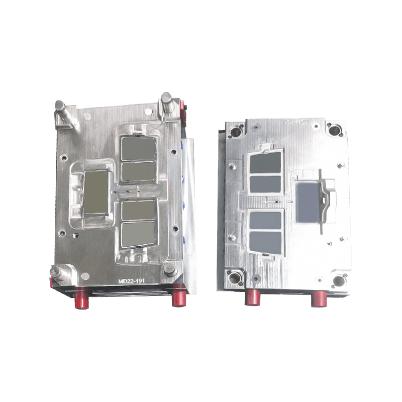
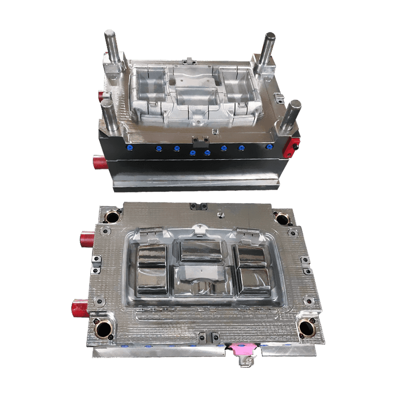
Toolbox storage box lid molds are essential components in the manufacturing process of toolboxes and...
See Details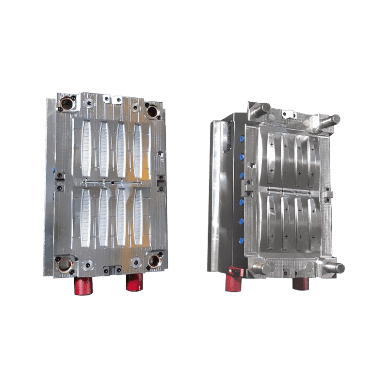
Toolbox handle trim molds play a crucial role in enhancing the functionality, aesthetics, and ergono...
See Details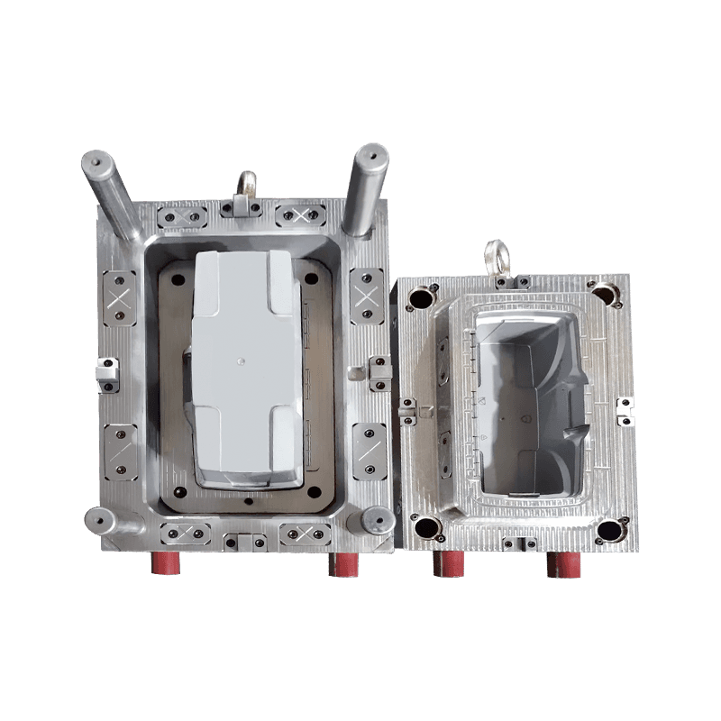
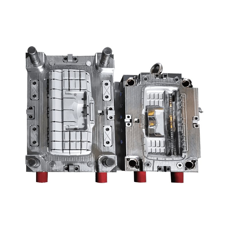
Toolbox shell molds play a pivotal role in the production of the outer casing or shell of toolboxes....
See Details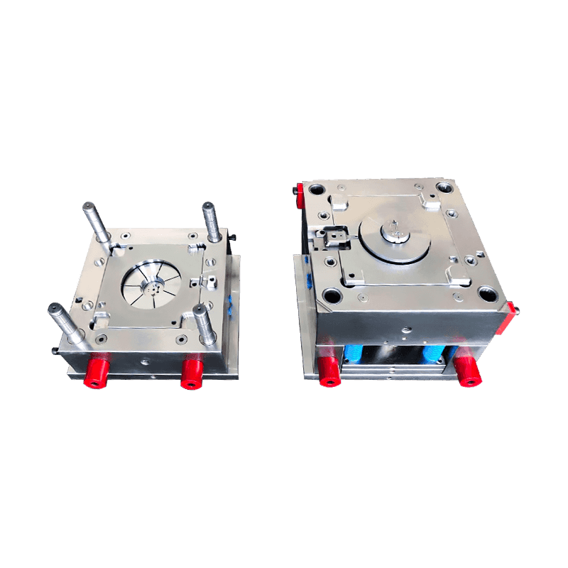
Ventilation fan molds are essential tools used in the manufacturing of ventilation fans, which play ...
See Details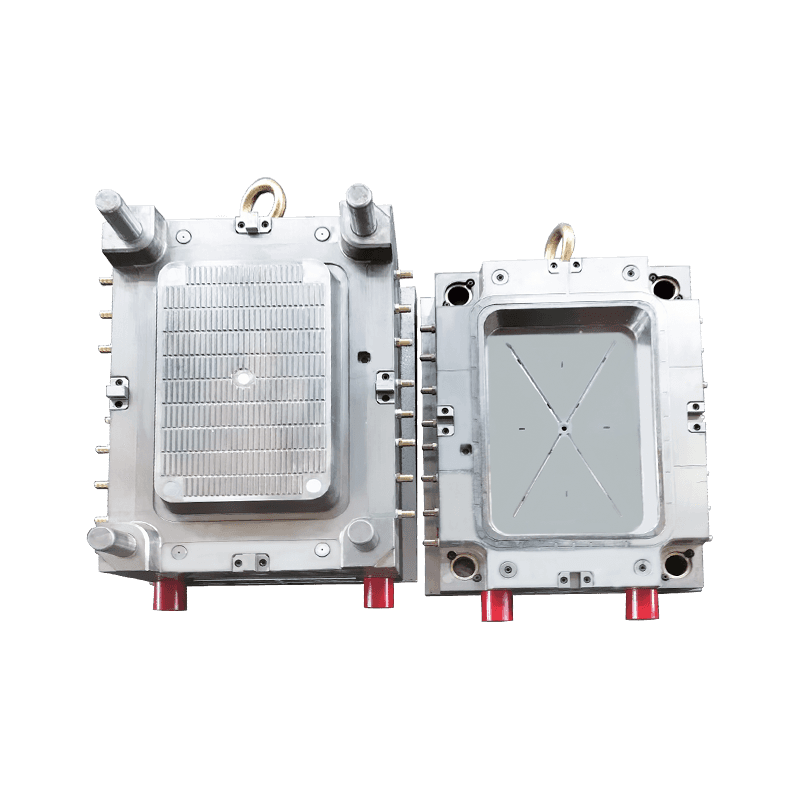
The design of the fruit and vegetable washing basket mold is crucial in balancing practicality and a...
See Details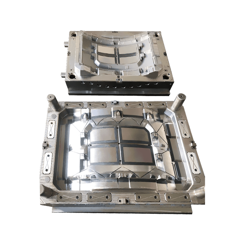
Seedling planting box molds play a crucial role in the cultivation of flowers, vegetables, and fruit...
See Details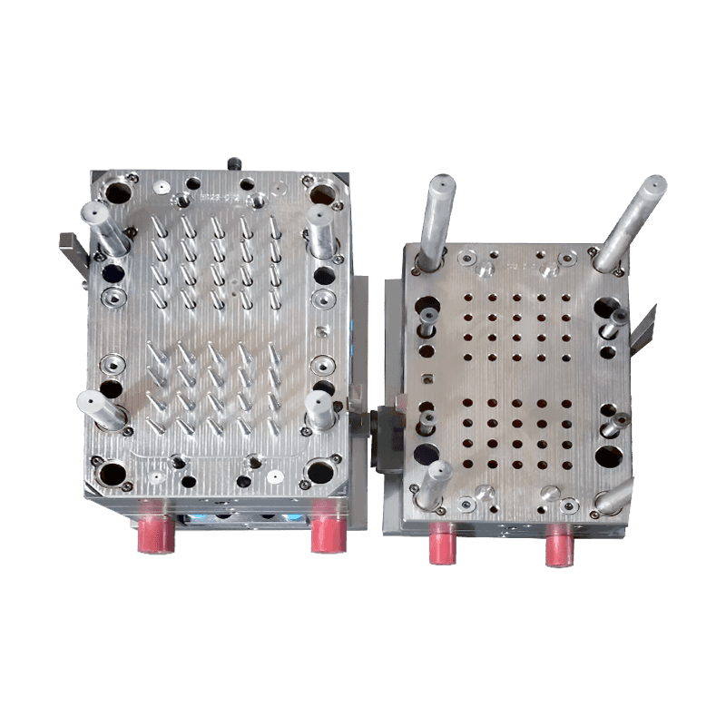
Production Capabilities and Quality Testing Standards for Medical Test Tube Mold Factories:A medical...
See Details+86-13616882963
We are committed to providing customers with high-quality, precision mold solutions.
Copyright © Taizhou Yiwei Mold Co., Ltd. All Rights Reserved.

Contact Us